
Michigan Scientific Europe / Application guide
How to measure torque on a rotating shaft?
Torque is most often measured with strain gauges bonded directly to the shaft. The problem: the gauge bridge rotates with the shaft while the signal conditioner and data acquisition system stay put. You therefore need to carry an analog signal of a few millivolts across a rotating interface — without degrading or delaying it.
Choose the architecture
Three ways to transmit the torque signal
Michigan Scientific manufactures all three technologies — slip rings, wireless telemetry and fiber optic systems. The choice depends on your mechanical layout, test duration and environment, not on a catalogue preference.
Slip ring
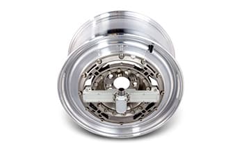
Continuous electrical connection through precious metal ring/brush contact, mounted on the shaft end or through-shaft.
- Continuous transmission with no delay and no bandwidth limit
- No on-shaft power supply to manage
- The simplest and most cost-effective solution in most cases
- Maximum contact noise 0.1 Ω (instrumentation quality)
- Requires mechanical access to the shaft (shaft end or through-shaft mounting)
- Mechanical contact: wear after 50 to 100 million revolutions
Wireless telemetry
The gauge bridge signal is digitized on the shaft and transmitted by radio (2.4 GHz) to a stationary receiver. Battery or induction powered.
- No mechanical link: suits inaccessible shafts or large travel (vehicle half-shafts)
- Clamp-on systems install without disassembling the driveline
- On-shaft power needed (24-48 h battery or induction hoop)
- Higher cost and complexity
- RF environment must be managed
Fiber optics
Optical signal transmission, fully immune to electromagnetic interference.
- Total EMI immunity
- Suited to electrically harsh environments (high voltage, electric machines)
- More complex and more expensive to implement
- Best reserved for cases where slip rings and telemetry reach their limits
In real conditions
See the integration before choosing the reference.
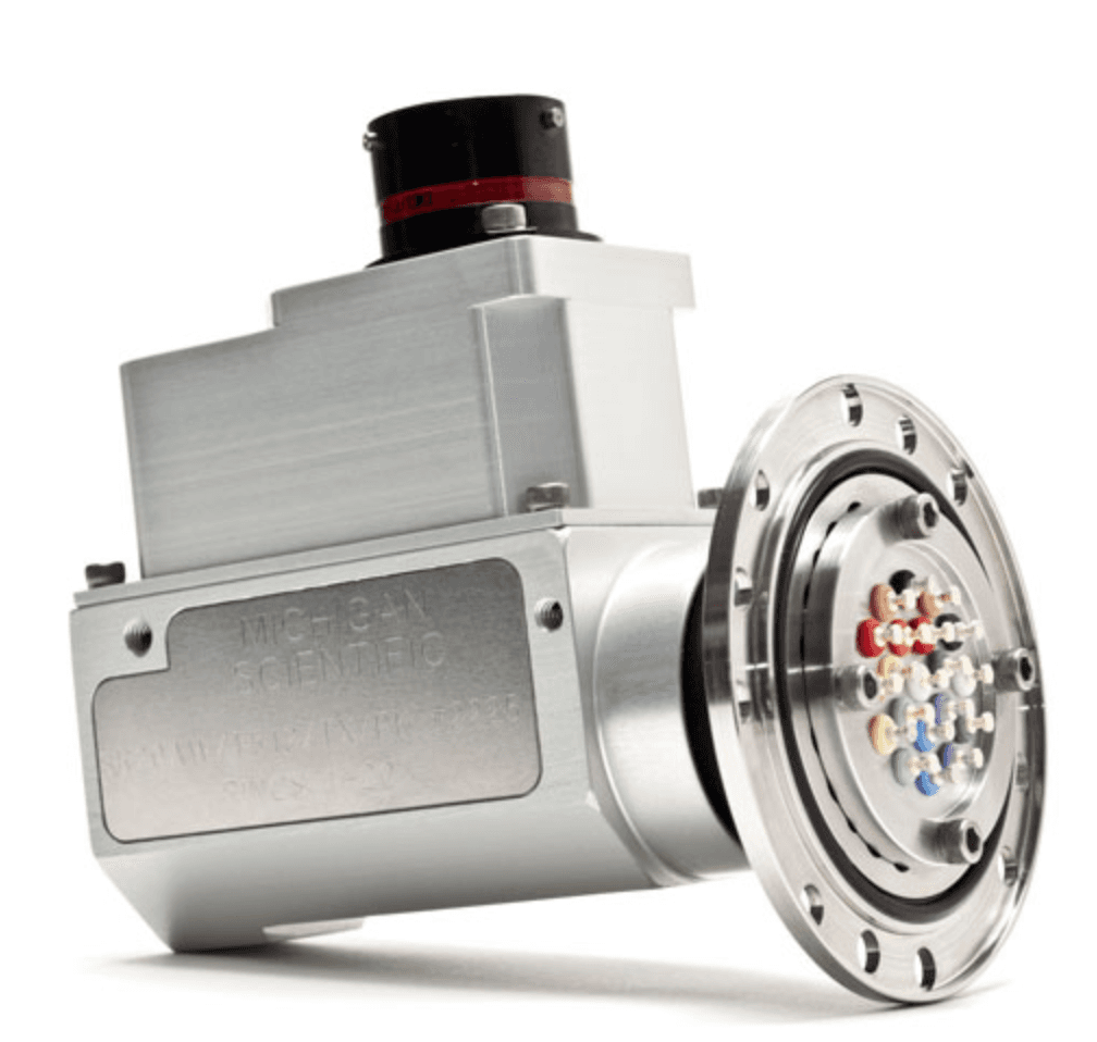
The slip ring sits between onboard instrumentation and stationary acquisition. This visual view helps validate the footprint, mounting and signal routing from the earliest design stages.
Why the slip ring is often the best choice for torque
A full strain gauge bridge only needs four circuits: a configuration covered by every Michigan Scientific slip ring, from the compact S4 to the SR36M. Precious metal rings and brushes keep contact resistance stable (0.1 Ω maximum noise), which is essential when working with millivolt-level bridge signals.
Direct-contact transmission introduces no delay and no filtering: the dynamic torque signal (torsional irregularities, shocks, gear shifts) reaches the data acquisition system intact. And for mechanical power calculations, encoder versions provide shaft speed on the same mount.
- Compatible with full, half and quarter bridges
- No signal delay: faithful dynamic measurements
- Embedded bridge amplifiers available (S6/G, S8/2Gx)
- 60 ppr encoder option: torque + speed = mechanical power
Next step
Your selection, already oriented to this application.
The signal type is prefilled from this guide. Simply refine the mechanical constraints and test conditions to find the suitable references.
Going further (technical documentation)
01What accuracy can I expect through a slip ring?
The slip ring only adds a contact resistance variation of 0.1 Ω maximum. On a typical gauge bridge, its contribution stays well below the other uncertainty sources in the chain (gauge bonding, calibration). [DATA TO BE CONFIRMED: typical uncertainty observed on a test bench]
02Can I measure torque AND speed to calculate power?
Yes. Encoder versions (B4-2/E60, SR/E60, SR__/PE512) deliver a speed signal on the same mechanical mount — 60 pulses per revolution for E60 versions.
03What if my shaft has no accessible end?
B-Series tubular slip rings mount through-shaft, directly on the shaft (⌀ 50.8 or 81.3 mm). Beyond that, clamp-on telemetry is the alternative: it installs without disassembling the driveline.
Related use cases
Talk to an engineer
Tell us about your application
Describe your measurement need: an engineer will get back to you with a concrete recommendation (model, configuration, quote).
- Reply within 1 business day
- Validation of your measurement chain
- Matched reference, options and quote
Or call us directly: +33 1 46 91 93 36